
The motor wires were connected in the order [RED, YELLOW, GREEN, GREY]. I guessed a bit on the location of pin one for each of the terminal blocks. Here is the final layout:

I drove the Arduino via USB (+5V), and the motors off of a separate lab power supply (+12V):

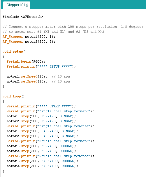
For the code, I kept the first scenario fairly simple; Sample code from the vendor was borrowed and modified to alternate the motors, driving them both forward and reverse. The code is below:
For this build, the impossible happened: everything worked the first time. The next steps will involve figuring out some kind of drive mechanism to make the steppers do something productive (well, more productive then rotating two blue painters tape flags). Since I have degrees in EE not ME, I'll need to spend a bit more time deciphering the right lingo for google queries (actuators, drive screws, linear bearings, etc., etc.)
No comments:
Post a Comment