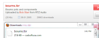
With only a small amount of components, building the LCD panel schematic was a quick process. I already knew that I wanted to connect the panel via some custom wires (more on that in a later post), so most of the board consists of 0.1" headers. The only piece not already in Eagle was the Bourns trimmer resistor [Mouser #652-3386F-1-103TLF]. After a trip to google, I found an Eagle PCB Search site which had a link to a library containing the 3386 series components. The library was hosted at Cadsoft USA, so a few clicks later I was downloading the parts library, and dumping it into my Eagle installation's LBR directory:
The final list of Eagle components needed for the schematic was:
- 2 x PINHD-1x2
- 1 x PINHD-1x4
- 1 x PINHD-1x16
- 1 x 3386-F (bourns.lbr)
The next post will discuss converting this schematic to a board.


No comments:
Post a Comment