Friday, April 3, 2020

Root 3 CNC - Installing the Endstops

The endstop wire assemblies were prepared in the last step.  Each of the limit switch bores was tapped for M3 screws, then installed to min/max positions on the machine.

X - Axis:


Y - Axis:


Z - Axis:


The machine wiring (pulled in a previous step) originates at the control panel and routes through the drag chains up to the endstop locations.  The wire ends were finished with JST connectors, and mounted with tie zips or anchors depending on their location.


Sunday, March 29, 2020

Root 3 CNC - Preparing the Endstops

Mechanical limit switches are used as my Root 3 CNC endstops.  These switches are readily available from any number of sources, see below for a link from Amazon:

10 Pcs 10x Spdt No Momentary Nc Hinge Lever Mini Micro Switches Dc Kw11 Kw12 A5


Since the components are small and prone to break over time, I spent a bit of time customizing the switches for easy replacement, and planned to install them in a "normally-closed" configuration (see NC vs NO).  For this layout, 3 wires are needed to return from the switch to the electronics shelf of the CNC: red, black, and braid/shield wire, so a 3-pin JST connector was used.  Due to the limited space, the terminal for the NO connection was removed from the switch so a capacitor could be installed easily between NC and COM.  The schematics based on this design are shown below.

The following wiring was used:
Wesbell Electroincs
CAROL-C0762
4C 22AWG FS DRAIN

The following JST connectors were used:
QLOUNI 2.54mm Pitch JST SM 2 3 4 5 Pin Male/Female Plug Kit


First the Limit Switch NO terminal was removed:


Then the capacitor, wiring and JST connector were soldered and assembled:


Finally the exposed NC and COM terminals were covered in liquid tape.  See the next post for documentation on installing the limit switches.

Root 3 CNC - Endstops Overview

Implementing endstops is where my Root 3 project was originally put on pause, so an argument could be made that I spent 18 months working them.  In reality it wasn't quite that long, but upon project restart I did spend a lot longer than I would have guessed at making the endstops behave.  Rather than trying to squeeze everything into one long post, I'll be breaking this topic up into a few component parts.

Note that everything I document is actually the second pass at building a solution.  For the first pass, I followed the standard Root 3 design and attempted to solder everything into a DB9 connector on the project control panel.  This resulted in a mess that never really worked reliably.  Apparently soldering 9 22awg wires into a DB9 connector is very tedious and prone to error if your soldering skills are rusty like mine...

Since I also wanted to run both min and max endstops for each axis in a "normally-closed" configuration, I decided to take a step back and design a different approach using DB9 breakout connectors and a breadboard soldering panel (see below).  This is completely over-engineered, but after my first DB9 soldering pass failed, I wanted to ensure success on the second pass.

CNC Endstop Panel


Electronics Cabinet Endstop Panel


Saturday, March 28, 2020

Root 3 CNC - Retroactive Posts

And just like that a year and a half went by... 

One of my kids started high school, another made a travel soccer team, and before you know it all my free time had vanished and 18 months disappeared in the blink of an eye.  As unlikely as it seems, the current pandemic placing a pause on planet Earth has actually given me some much needed time to think and get back to basics.

In my limited spare time I continued on with the Root 3 build, but at a snails pace.  I'm much further along and have a number of pictures to document the steps I have not documented to date.  Sometime soon I will retroactively make posts on the other major sections of the build.

In the meantime, I'll start posting with what I'm currently working on, and hopefully in a few months it will all even out...

Wednesday, June 27, 2018

Alternate between VMWare and Docker on Windows

If you decide you want to try out Docker on your Windows machine and already have VMWare Workstation installed, you will be in for an unexpected treat the next time you attempt to start one of your VMs:


As it turns out, Docker for Windows relies on Hyper-V (Microsoft's virtualization technology) which is a completely incompatible hypervisor with VMWare.  If you do some searching on the VMWare site, they are happy to show you how to totally remove Hyper-V in a knowledge base article.

If you want to do something a little less drastic, and alternate between the two products, you can simply disable Hyper-V.

Disable Hyper-V:
bcdedit /set hypervisorlaunchtype off
reboot Windows
(now VMWare will work, and Docker will not)

Enable Hyper-V:
bcdedit /set hypervisorlaunchtype auto
reboot Windows
(now Docker will work, and VMWare will not)

Make sure to run those commands from a command prompt that has been launched as administrator.  Not ideal by any stretch of the imagination, but if you are looking to have both capabilities on a dev workstation, this will get you through...

Wednesday, June 6, 2018

Root 3 CNC - Adding the Spindle Mount to the Z-Axis

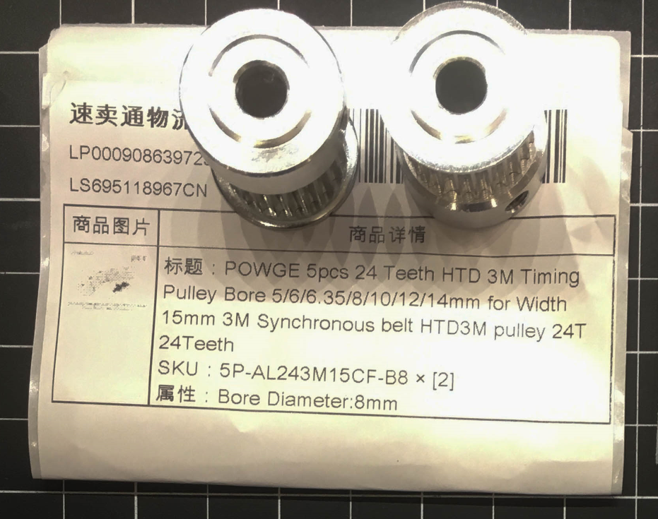
The 80mm Spindle Mount Assembly connects to the Z-Axis via the MGN12c linear bearing blocks, as well as the 8mm threaded trapezoidal lead screw.  Start the process by adding a 24-tooth 8mm 3M HTD pulley to the lead screw and securing it with a set screw.


Roughly set the spindle mount assembly in place.  Thread the lead screw though the top mount, through the spindle mount assembly, then finally through the bottom mount.  If your 3D Parts are a little warped/missized like mine were, you will need to drill out the holes on the spindle mounts a bit, to ensure they align with the MGN12c blocks.


To fasten the assembly to the MGN12c blocks, the following parts were used:

  • 16x M3 x 12mm screws (0.5mm threads)
  • 16x M3 lock washers
  • 16x M3 washers


The following picture is out of sequence (it was taken while testing part fittings/alignment) but is the only photo I have which demonstrates how the inner screws are fastened.  A Wiha precision screwdriver is inserted through the front of the 3D printed assembly to tighten the screw.  To help with alignment, another screwdriver was used as leverage to move the small M3 screws/washers into position before tightening.


Proceed with fastening all 16 screws.  For my build, I completed the 8 outer screws before attempting the inner screws.


Once fully attached, the trapezoidal lead screw can be cut to length.  Mark the appropriate location, and then use a hacksaw to remove the excess length.  Use a file on the finished cut to knock down any sharp edges.


Root 3 CNC - Building the Spindle Mount Assembly

To start the spindle mount assembly, the following parts were used:

  • 2x MGN12C 80mm Spindle Mount 3D Printed Parts
  • 2x M3 x 35mm screws (0.5mm threads)
  • 4x M3 nylon lock nuts
  • 2x Brass T8 Trapezoidal Screw Nut

For each of the 3D Printed Parts, fasten the T8 lead screw nut with 4 screws and lock nuts.


To combine the two parts into one spindle mount assembly, the following parts were used

  • 2x High-Strength Steel Threaded Rod 10-24 Thread Size, 4" Long
  • 8x 10-24 flanged lock nuts


Insert the threaded rods, and attach on both ends with a flanged lock nut:


Add the second spindle mount and surround with flanged lock nuts.  Temporarily add the 8mm lead screw to check alignment, and then tighten all nuts.


The spindle mount assembly is now ready for mounting on the Z-Axis: