Friday, August 23, 2013

Building an alternate nozzle for a Karcher K5.540 Power Washer

It seems like a rather odd thing to do, but in order to support a recent project, I needed to find a way to replace the gianourmous spray gun attachment which ships with the Karcher K5.540 with something a bit smaller.  The resulting sprayer nozzle looks like this when assembled:


The Karcher units are a little tricky as they use a proprietary fitting on their hoses.  Luckily, RJ Bowers carries a part (black piece above) which connects the high pressure hose via a quick connecter and terminates in a common M22 thread.

The four magic pieces used to assemble the sprayer gun replacement are as follows:
  • RJ Bowers: Karcher 4.470-041.0 (4470-0410)
  • General Pump M22 Male to 1/4" NPT Male Adapter (D10021)
  • Brass Sleeve-Lock Socket, 1/4" NPTF Female, 1/4" Coupling (6537K73)
  • Briggs & Stratton 6193 Quick Connect Spray Tips (6193)
The B&S quick connect spray tips come with a variety of angles:
  • Black - low pressure tip
  • White - 40 degree
  • Green - 25 degree
  • Yellow - 15 degree (seen in the above picture)
  • Red - 0 degree
The red tip is fairly useless unless you are planning to write your name in concrete.  The next most powerful is the yellow tip at 15 degrees.  The resulting spray is not quite as intense as from the original spray head (perhaps the nozzle output hole is too large), but is still respectable and has a much smaller profile.  In short, its perfect for the prototype system I'm working on.

I initially had some concerns about back pressure from the new head, but based on the results, I do not think it will be a problem.

Sunday, July 28, 2013

Enabling Amazon AWS Billing Alerts

To eliminate billing surprises at the end of the month, an Amazon account can enable billing alerts which will monitor usage and send notifications when threshold limits are exceeded.  This is done through the "Account Activity" page for the user.

Log into the AWS Console, navigate to the Account Activity page, and click "Enable Now".


The site will take a minute to process your request, and then alert you when the task is completed.


After alerts are enabled, on the same Account Activity page there will be a link to "Set your first billing alarm".


After clicking the link, a dialog will pop up; Press "Create Alarm" from here.


Fill out the form below; specifically, enter the email addresses where notification should be sent, as well as the US dollar amount which is your threshold.


After clicking "Create Alarm" on the dialog box, the alarm is created and enabled.


Disassembly of a Karcher 3.379 Power Washer

This weekend's fun consisted of breaking down an old electric power washer;  I have need of the high pressure water pump for a new project.


The breakdown went much quicker than anticipated.  The soap feed bottle just pops out, and the handle came off after removing two slotted screws at the base.


After the handle was off, the black accessory case on the back slid off (towards handle) with a few taps from a rubber mallet.


Then a T-15 screwdriver was used to remove about a half-dozen screws holding the two sides of the outer shell together.


With the case off, the water pump lifted out easily (nothing holding it in place except for the plastic casing being snug all around).


With the pump out, there was an elbow held in place with a "shim key" which was used to get the outfeed connector outside of the yellow plastic case.


Finally the hand wand attachment was disassembled in order to see how the outfeed water supply works.  As it turns out, just a few plastic moldings and springs holds the entire works together.


I'm not entirely sure what I was expecting when I started the disassembly, but I'm fairly sure I was expecting something a little more complex than a water pump held together with about $5 worth of injection molded plastic.  In any event, I now have a much better understanding of power washers, and even have a salvageable high-pressure water pump to be re-used in another project.

Sunday, June 30, 2013

Driving a Trapezoidal Lead Screw

With the motor shield assembled and stepper motors in hand, I ordered a number of mechanical parts and waited almost 2-3 weeks for everything to arrive. Some of the key parts in use are as follows:
It took an afternoon to cut/measure/assemble all of the parts.  Unfortunately I was thinking a bit too much in 2 dimensions when I ordered the parts, and did not account for the height differences that would come into play during final assembly.  In order to place the stepper motor and mated bearing at the correct locations, I cut down some scrap pieces of 2x4 lumber I had remaining from a different project -- a bit of a sloppy hack, but it worked fine.  The final assembly is shown below:


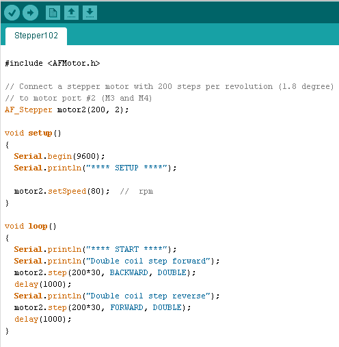
To drive the motor, the following code was uploaded to the Arduino board:


To my great surprise, everything worked as expected the first time the system was powered up.  The unit was a little noisier than expected, but I think that may be due to a slight misalignment of the flange nut and its associated vibrations.  In the future I'll try to track down a washer to install between the flange nut and plastic angle to reduce vibration and help compensate for the noise (building something a little more exact that a hunk of 2x4 wouldn't hurt either).

Next up will be to determine what to use for limit switches so that the unit can travel from end-to-end (and not just travel back-and-forth in a coded fixed length) - either a physical switch or a Hall-effect sensor are the likely final candidate.  I'll also need to determine some better wire quick connects to easily connect/disconnect the electronics.

Friday, June 7, 2013

Driving 12V Stepper Motors

With a motor shield fully assembled (see earlier post), it was time to connect up 2 x 12V stepper motors (purchased here) and see if the soldering job was all goodness.


The motor wires were connected in the order [RED, YELLOW, GREEN, GREY]. I guessed a bit on  the location of pin one for each of the terminal blocks.  Here is the final layout:


I drove the Arduino via USB (+5V), and the motors off of a separate lab power supply (+12V):


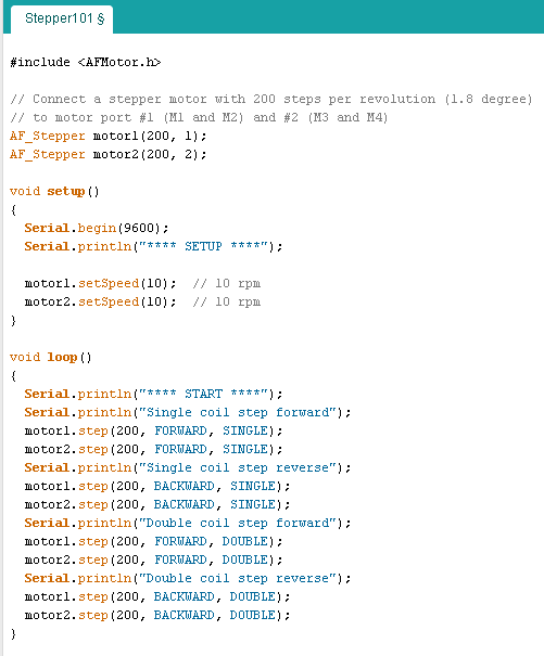
For the code, I kept the first scenario fairly simple;  Sample code from the vendor was borrowed and modified to alternate the motors, driving them both forward and reverse.  The code is below:


For this build, the impossible happened: everything worked the first time.  The next steps will involve figuring out some kind of drive mechanism to make the steppers do something productive (well, more productive then rotating two blue painters tape flags).  Since I have degrees in EE not ME, I'll need to spend a bit more time deciphering the right lingo for google queries (actuators, drive screws, linear bearings, etc., etc.)

Thursday, June 6, 2013

Assembling an Adafruit Motor Shield for Arduino

I guess my first clue should have been in the name "Adafruit Motor Shield Kit", but somehow my eyes rolled right over the last word.


The motor shield arrived as a PCB, 3 ICs, and a handful of passive components, meaning it was time to break out the soldering iron.  The kit assembled without too much trouble, with full assembly instructions online.  The online instructions appear to be for an earlier edition of the board, but it wasn't too hard to decipher the differences.

The only part of the directions that were unclear was a statement that "the four 'middle' pins of the L293D motor driver chips are tied to a large heat sink and thus may end up getting 'bridged' with solder as shown in the second image."  I wasn't sure if that meant you were supposed to bridge the pins, or it was just something that just may happen.  A little digging on the forums revealed that the pins in question are all GND, so it doesn't really matter whether they get bridged or not.

BEFORE


AFTER


I thought about showing you the outstanding soldering job on the back of the board, but decided instead to blame the camera for taking a poor picture, which has no relation to the high-quality soldering which actually occurred on this assembly.  I also installed a set of stacking headers in the extra provided through-holes, and cut them short on the back as they will not be used for stacking; since I've never worked with motors before, I'm guessing I'll have need of the convenient headers for debugging.

Next up will be the connection of the stepper motors and a sample sketch to get them moving, after of course reading the manual.

Friday, May 31, 2013

Ditching the Ubuntu Unity UI

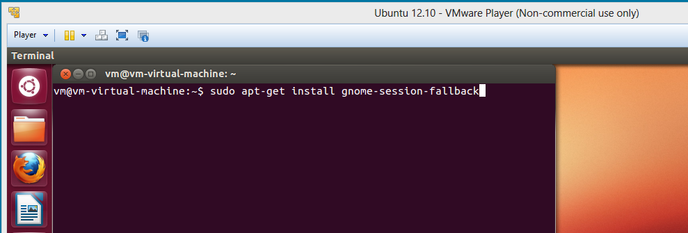
It seems to be the decade of the bad OS UI; between Windows 8 and Unity, I'm about ready to swear off UIs and stick to command prompts.  Here are some quick notes on how to get the Unity monstrosity off your Ubuntu desktop.  First open a terminal window, and run

sudo apt-get install gnome-session-fallback


After restarting the machine, click the Ubuntu logo from the login screen (on the upper right):


and you'll be greeted with another menu:


Select GNOME Classic, followed by OK.  After logging in, Ubuntu will be "back to normal".