Sunday, January 17, 2021

Installing Drivers for an Arduino Nano Clone

I recently started a new project, and the quickest way to get an Arduino Nano delivered was to get a "knock-off" board.  The specific one I used was purchased from Amazon:


Everything looked normal when it arrived, but I could not get the Arduino IDE to recognize the device via USB (the port menu remained greyed out in the IDE).  It turns out this board uses a alternate communications chip which was missing drivers on Windows 10.

Original ATmega328P CH340 chip is used. Improved new version CH340G Replace FT232RL.

After a bit of searching, I found link on SparkFun to download/install the CH340 drivers.  After the drivers were installed, the Arduino IDE recognized the Nano and all was right with the world...

Sunday, December 27, 2020

Building an OctoPrint Server

 This is a followup to the 2018 post which documented the build of a RPi3 OctoPrint server for a Lulzbot Mini.  This post documents a new 2020 build to upgrade the device.

Hardware:

Software:

The OctoPrint server was downloaded from here.  Upon installing 0.17.0 and booting, I was greeted with a set of 4 long blinks followed by 4 short blinks on the system LED.  Its a bit like decoding Morris Code, with the blink patterns documented here. In my case, I was receiving an "unsupported board" message.  Luckily the following disclaimer appears on the download page, and I was glad it was documented (saving me the time of tracking down the problem):

There have been some reports regarding current revisions of the Raspberry Pi 4 1/2/4 GB refusing to boot with the stable OctoPi 0.17.0 image. If that affects you, please try the OctoPi 0.18.0 release candidate.

The problem was resolved by downloading and installing the 32 bit 0.18.0 release candidate. 

Setup:

Directions on the download page were followed to change the Pi's password, hostname, network configuration, and time-zone.  Rather than wasting time configuring the Pi with a static IP address, I instead chose the route of hacking an entry into the hosts file of my laptop (%WINDIR%\system32\drivers\etc).  I installed one additional plugin, a resource monitor for OctoPrint:


which provides a "Windows Process Manager-like" display for the RPi:

After initial configuration, everything was working as expected except for the connection from my slicing software (Cura for the Lulzbot Mini).  I needed to update the OctoPrint configuration to account for the new IP address as well as API Key.

In OctoPrint:


In Cura:


It appears there is a new option for creating a "non-global" access key, but that will be an enhancement for another day...

Thursday, August 20, 2020

Building a Bench Power Supply with the RD6006

I decided to finally upgrade the old home-made switching power supply I've been using for the last 20 years (at some point it becomes more of a fire hazard then a power supply).  Luckily components are a little more readily available these days, and I chose the Riden RD6006 controller.  You can find the components more reasonably priced here (if you can wait a month for shipping):

RD Riden Factory Store

or pickup the components on Amazon (a fairly steep markup, but it will be at your house tomorrow):

RD6006 Controller

60V Power Supply

Case

CR1220 Battery

PC Power Cord

After unboxing and testing the power supply with a test cable, the power supply was ready to assemble:

First install the switch, power terminal, and case fan:


Mount the power supply:


Add the case feet (so the supply screws don't scratch up your desktop):

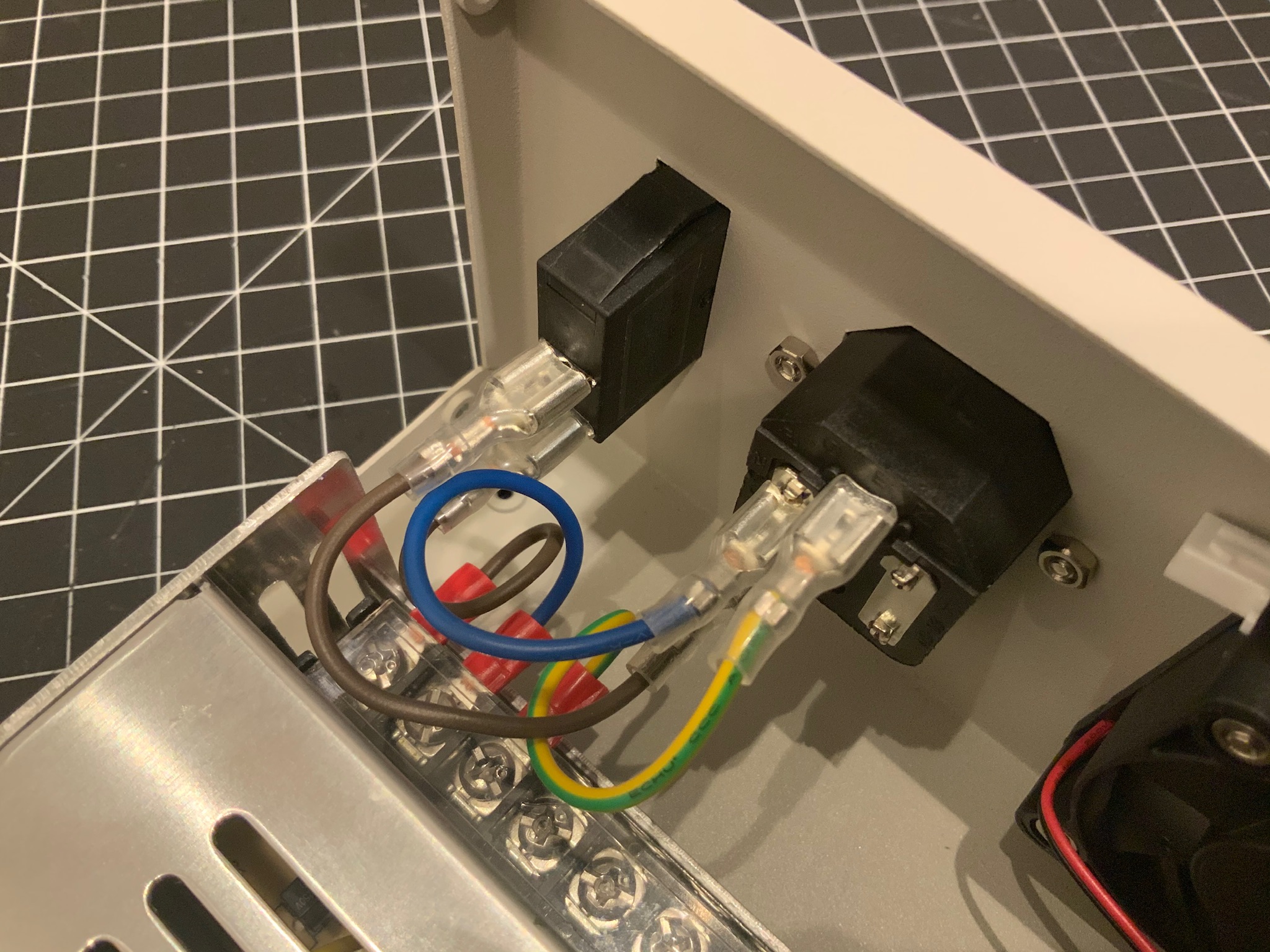
Wiring took a little bit to figure out; the marking is camouflaged fairly well, but if you look closely you can see an E (for earth ground) and N for neutral (leaving the last terminal being hot):

The jumper cables from the kit were sized correctly:


Next install the case fan temperature controller:


And wire directly to the supply:


The power terminal was pulled from the controller and wires added from the case kit:


Power cable connected to the controller (making sure to honor polarity on the PCB):


Add a CR1220 battery as the mount is beneath the WIFI module:


Install the WIFI module:


Add the controller temperature probe:


Before closing up the case, power it up and make sure all is well:


A project is never done until the wire wraps go on...


Fully assemble the case:


Note that I had a bit of trouble getting all the parts together - the controller JUST fits within the case, and the case is not 100% square, so there was one case screw I just could not get aligned.  All that being said, I'm fairly pleased with the result.

The manual can be found here from the vendor:

And this video was also useful:

Wednesday, August 5, 2020

Root 3 CNC (Retro) - Cloning the Marlin Repo

This is a retroactive post from earlier in the build process...

The Root 3 CNC firmware is a fork of the Marlin baseline, clone from GitHub.


Root 3 CNC (Retro) - Powering the Arduino/RAMPS Controller

This is a retroactive post from earlier in the build process...

Nothing too complex here, just running two +5/GND pairs from the power supply to the board...


Root 3 CNC (Retro) - Installing the Marlin LCD Display

This is a retroactive post from earlier in the build process...

Installing the LCD required both hardware and software tasks to be completed.  First the LCD panel was encased in a protective covering (many open source options on Thingiverse):


Then software changes were required in the Marlin firmware to enable the LCD:


The #define statement for the controller was uncommented, and the U8glib library was installed from GitHub.


Root 3 CNC (Retro) - Installing the X-Axis Belt

This is a retroactive post from earlier in the build process...

The X-Axis belt was installed mostly per specs.  The only change was that the original x-axis belt clamp was modified to re-enforce the center of the part.