Thursday, July 23, 2020

Root 3 CNC (Retro) - Motors

This is a retroactive post from earlier in the build process...

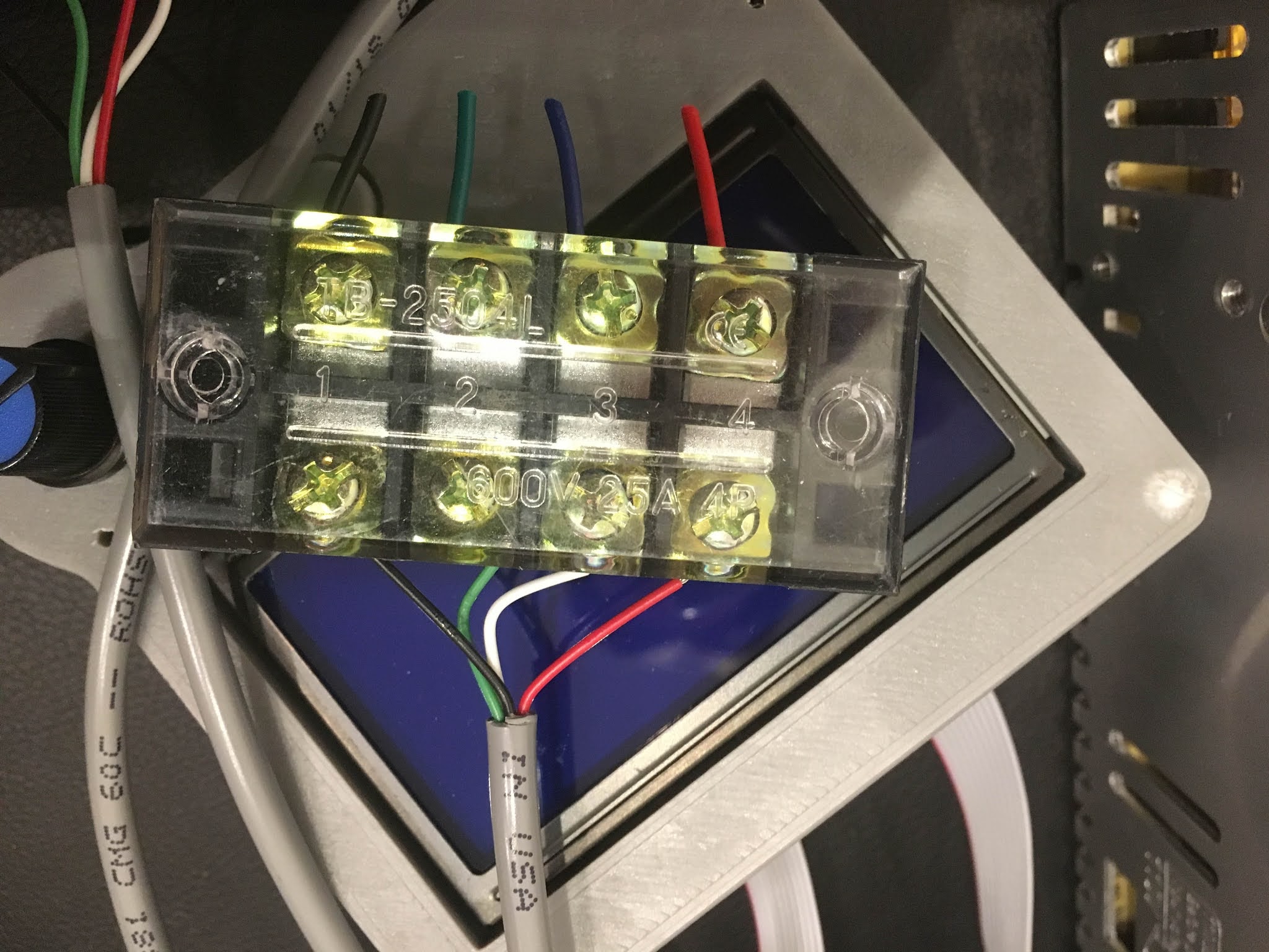
The motors used for this project are found here Nema 23 Bipolar 1.8deg 2.4Nm (340oz.in) 1.8A 4.95V.  The screw terminals are found on Amazon.  The wire used was WesBell PVC Shielded Cable 4C 22AWG (CAROL-C0762).


Tuesday, July 21, 2020

Root 3 CNC - Step Calibration

When setting the Marlin step parameters, the initial values were chosen based on default calculations.  Now that the machine is built, the value can be tweaked based on the realities of the CNC performance.  A simple 2 1/2d square (10cm x 10cm) was designed and cut.  Measure the X and Y dimensions of the final piece, and then use those values to adjust the step parameters.

new steps = (current steps) x (requested movement/measured distance)

If you have 93 step/mm as now, and you measured 101.3mm with a 100mm designed movement, you do : 93 x (100/101.3) = 91.8 is the new parameter.

Sunday, July 19, 2020

Root 3 CNC (Retro) - Installing 8825 Motor Drivers

This is a retroactive post from earlier in the build process...

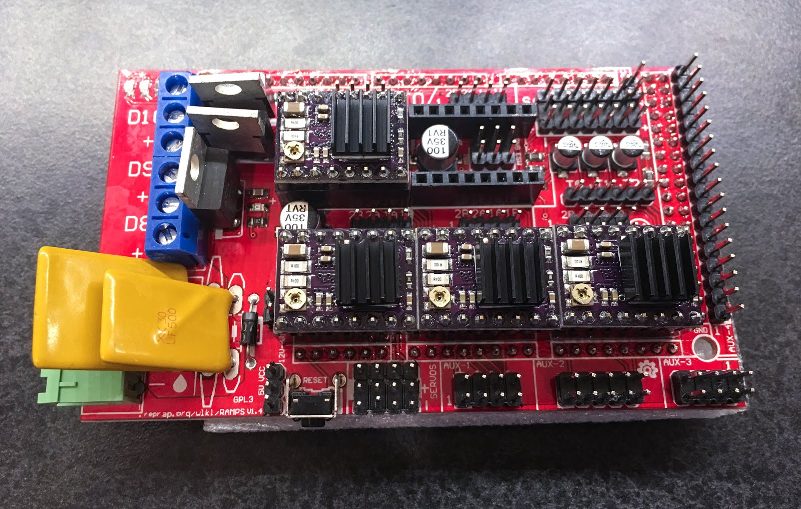
Pololu DRV8825 motor driver chips were installed on the RAMPS board to control the NEMA23 steppers.  Before being installed, the chips must be bench configured to set the maximum current.  This was done by a temporary breadboard setup, where the voltage could be changed and monitored by an onboard potentiometer screw.


For my stepper motors, a voltage of 0.9V provides the correct amperage:


Once configured, the DRV8825 drivers could be installed on the RAMPS board:


As a last step, heat sinks were installed on the driver chips:

Root 3 CNC (Retro) - 12V Power Supply

This is a retroactive post from earlier in the build process...

A 12V supply is needed to power the Arduino/RAMPS as well as the stepper motors and cooling fans.  The unit chosen for this product was a 12V/30A eTopxizu found on Amazon.

An old computer CPU power cable was repurposed by removing the connector and adding ring terminals in its place:


Friday, July 10, 2020

Root 3 CNC - VFD Wiring

Some of this information was already documented in the post "Programming the HY02D211B VFD", but this entry is meant to be a full reference on the VFD/Spindle wiring connections.

The wiring panel is accessed by removing two case screws on the VFD:


This particular VFD connects to 110V and converts it to run the spindle at 220V.  A 12/3 SJOOW cable was purchased and connected as follows:
  • Black (HOT) to R
  • White (Neutral) to T
  • Green to Ground


The spindle aviation connection pins are numbered as follows:


In addition to the 4 wires (3 hot plus ground), there is a 5th wire which is the control cable shield braid (GREEN+WHITE WIRE = BRAID), which also needs to connect to ground.  The following table lists the connections:

SPINDLE  WIRE    VFD
1                 2             U
2                 1             V
3                 3             W
4                GRN       GND
                  BRAID   GND


Ultimately there were too many ground wires to connect directly to the VFD.  A pigtail wire was installed from the VFD GND, and all of the remaining wires were bundled.  Initially a wire nut was used for testing, however, that was replaced with a WAGO connector for safety purposes.

Root 3 CNC - Test Pieces

A test piece was designed in Fusion 360 to do the initial testing and calibration on the machine.  It is a 10cm circle next to a 10cm square.  The circle has a center bore, and the square has a slot, with the two pieces connected with a small bridge.

The first test-run started well, but finished quite poorly, as the spindle went of course on the last run of the toolpath:


I thought maybe the feed rate was too high, so slowed it down and added a few more passes to the depth.  This actually made things worse:


The X-Axis belt was tightened.  While examining the machine after the 2nd run, it was noticed that the Y2 motor was not warm.  After investigation, a wire was found that had come loose, meaning the Y1 motor was pushing the entire spindle assembly from one side only.  The wire was tightened, and the test piece run two more times:


By the 4th print, things are looking a lot better (sure helps using both Y motors).  Measuring the X and Y dimensions, the test piece is off between 0.5 and 1.0mm.  This information will need to be included into the X+Y step calculations in order to get the CNC cutting more accurately.


Root 3 CNC - Base Threaded Inserts

In order to provide mount points for work pieces, brass M8 threaded inserts were purchased for installation on the base:


Using Microsoft Excel, a small gcode program was written to generate a grid pattern on the base, which was drilled with a 1/8" rotozip bit (endmills had not arrived yet):


These inserts required an 11mm hole, so using a metric bit and a 3-D Printed manual drill press, the pilot holes were expanded.  An impact driver using an installation bit was used to sink the inserts into the plywood:


Finally, a surrounding row of inserts was manually added outside of the milling area:


The base with most of the inserts installed: